Spatial Fuser Pipeline
LiDARMill’s Spatial Fuser Pipeline uses the trajectory data generated by NavLab, combined with LiDAR and imagery data from your system, to generate a calibrated, classified and colorized point cloud. Spatial Fuser can also produce data products in the form of DTM/DSM, Contours, decimated pointclouds and more.
It is possible to initiate a Spatial Fuser pipeline before the NavLab pipeline finishes processing. Select your "processing" trajectory when creating your pipeline, and LiDARMill will automatically start the Spatial Fuser pipeline when the NavLab pipeline is complete.
Video Tutorial
Select Spatial Fuser Postprocessing
To begin processing your LiDAR data, create a Spatial Fuser Pipeline by navigating to the Pipelines tab. Under Select Processing, choose "Spatial Fuser". LiDARMill indicates the types of input files required, and the type of output file that it will create. Click "Next" to move forward.
Select Input Files/Artifacts
Spatial Fuser requires a trajectory and LiDAR data. It can also utilize Camera data, and ground control points if present. Once you've selected all the files you'd like to use in processing, click "Next".
Configure Parameters

Pipeline settings
Specify the Pipeline name and configure the Dataset type (Aerial or Mobile) to optimize processing

Calibration
Used to override the system calibration configured at the time of data acquisition, if needed.

LiDAR Settings
Use full LiDAR density: Settings from the PLP will be overridden for achieving full lidar density (ignoring the PLP's laser-beam selection, frustrums, echo-selection, reflectance-filter and range-filter defined in the LiDAR>Processing tab within SE). Disable this if you want to use settings that were previously defined in the uploaded PLP.
Configure the desired Downward Field-of-View in degrees (90 recommended for aerial acquisitions), as well as the desired LiDAR Range from sensor (Min/Max in meters), to be included in the generated pointcloud.

Flightlines
Configure flighlines containing lidar data which will be included in the generated pointcloud

Automatically split flightlines: LiDARMill automatically splits your trajectory into multiple intervals each containing LiDAR data that was captured during straight flightlines of a minimum time duration that the user specifies.
Manually split flightlines: Enable this tool and then click the "Compute trajectory flightlines" button to specify which flightlines should be included in the generated pointcloud
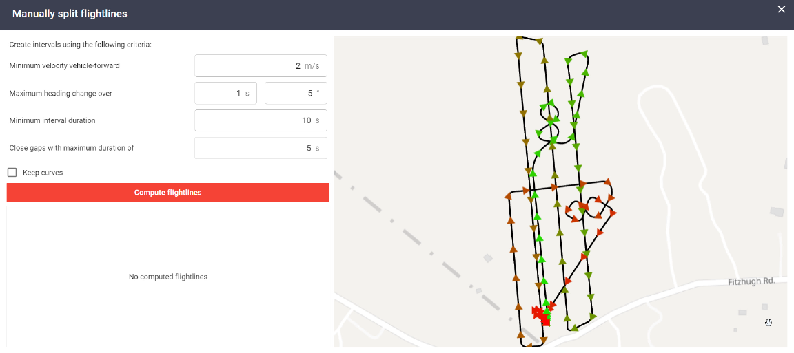
Specify Autosplit trajectory criteria and then click "compute flightlines".
Note: You can reconfigure parameters and click "compute flightlines" to recompute autosplit intervals.
The red lines indicate the intervals that will be used to generate the pointcloud
Disable the checkbox next to the flightline name to exclude undesirable intervals
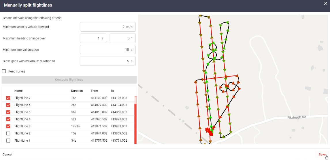
Click "Save" at the bottom right to finalize selection
Optimization
Trajectory optimization: Performs feature matching within overlapping swaths of LiDAR data to determine correction offsets that are applied to the mission's trajectory to improve point cloud relative accuracy.
In general, it IS recommended to enable trajectory optimization on most datasets to improve the relative accuracy of the resulting pointcloud.
Optimization may not produce desirable results in cases where the dataset is exceptionally noisy, a large portion of the scanned area contains water bodies, or if the majority of the scanned area contains vegetation so thick that only an extremely low number of ground returns are present.
Use GCPs with LS4: Uses GCPs during trajectory optimization to determine the necessary vertical adjustment.
Compare GCPs (check/control points) only against ground classified points: When point cloud elevations are compared to GCPs, this feature ensures that GCPs residuals are calculated only against ground classified points. This is useful for preventing erroneous vertical shifts, typically caused by point cloud data being present above or below a GCP (high vegetation, reference stations, etc.).
Sensor Calibration (boresight optimization tool): Applies an angular correction to LiDAR sensor (pitch, yaw, roll correction) to resolve misalignments from IMU to sensor. Depending on the LiDAR model, an additional ranging scale correction, tilt angle offset, or encoder calibration correction may be calculated and applied.
In general, it IS NOT recommended to enable sensor calibration, unless a specific boresight calibration pattern was flown as part of the mission.
Enable Photos in Turns: Option to enable/disable photos acquired during turns
Ground Classification
The iteration parameters of the ground classification routine determine how close a point must be to a triangle plane to be accepted as a ground classified point

Iteration Angle: Iteration angle (degrees) is the maximum angle between a point, its projection on the triangle plane, and the closest triangle vertex. It is the main parameter controlling how many points are classified into the ground class. The larger the iteration angle, the denser the resulting ground classification. The smaller the angle, the less eager the routine is to follow variation in the ground level, such as small undulations in terrain. Use a smaller angle in flat terrain and a bigger value in mountainous terrain (Recommended value range: 4 - 12).
Iteration Distance: Iteration distance (meters) ensures that the iteration does not make big jumps upward if triangles are large. This value is expressed in meters with a larger iteration distance including more low vegetation points within the ground model (Recommended value range: 0.1 - 0.5).
Max length of building: The max length of building (meters) parameter defines the search area for initial ground points. The input value should be close to the longest edge length for the largest building in your scanned area (Recommended value range: Typically 20 - 100 meters).
Ground Thickness: How much algorithm should thicken the final ground. Should reflect expected ground thickness.
Feature size: Cell size for initial TIN creation. Smaller values increase memory consumption, but improve the algorithm's ability to climb slopes.
AI Classification (Beta): AI classification leverages a neural network to infer point classification. Classification accuracy depends on the type of terrain/geometry and cloud accuracy, but usually classifies around 98% of points correctly. Classifications currently include:
Unclassified
Ground
High vegetation
Building
Low point (noise)
Shield wire
Transmission Wire
Transmission Tower
Wire Structure Connector (insulator)
Car
Guy wire
Fence
Lamp post
Classify Moving Objects : Checks whether points have neighbors from different intervals within a default search radius. This removes moving objects, such as pedestrians and moving vehicles, which will not appear in the same position in different intervals.
Alternative Classification : Uses an alternative classification algorithm to extract ground classified points from the rest of the point cloud. With ground points classified, the advanced classifier can determine and store other attributes such as "normalized height" and "height above ground" within the output file.


LiDAR
It is recommended to use the default parameters populated here. If you acquired data in the incorrect rover profile, however, you could correct for that by editing the parameters here.

Note: Lever arm offsets are now measured along the IMU axis. For the "Rotation" section, rotate the sensor frame into the IMU frame by rotating around the sensor axes in ZXY order (rotate around rotated axes for the 2nd and 3rd rotation). Refer to the "Orientations and Offsets" section of the user manual for more information
Camera

Disable: Camera data will not be used during processing when enabled
Override Settings: It is recommended to use the default parameters populated here. If you acquired data in the incorrect rover profile, however, you could correct for that by editing the parameters here.
Note: Lever arm offsets are now measured along the IMU axis. For the "Rotation" section, rotate the sensor frame into the IMU frame by rotating around the sensor axes in ZXY order (rotate around rotated axes for the 2nd and 3rd rotation). Refer to the "Orientations and Offsets" section of the user manual for more information
Calibrate Camera: Camera calibration requires correctly setting initial focal length. For Camera Calibration to succeed, images need to contain mostly manmade features and little vegetation. If collected imagery has sufficient overlap and sidelap (50% or more) it is recommended to enable "Calibrate Camera".
Per Exposure Pose Correction: Optimizes each individual photo's orientation to minimize errors between all photos. Recommended to keep enabled.
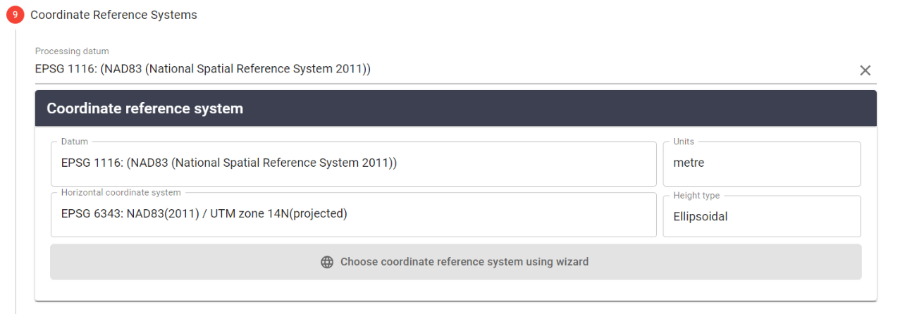
Coordinate Reference Systems
The processing CRS automatically defaults to the configured project CRS.
Products
Use this section to select and configure desired output data products.
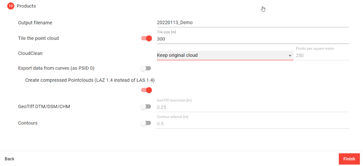
Tile the point cloud
When enabled, this tool will automatically tile the output dataset into squares with a user specified edge length (Tile size). This is beneficial for large datasets. You can view and download tiled data by clicking on "Select Tiles" next to the Spatial Fuser pipeline.


CloudClean
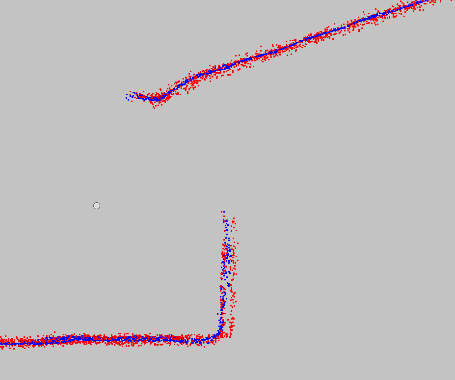
Fits a mathematical model of a surface to the original points of the point cloud, with the aim of representing the true surface as best as it can, by excluding ranging noise. Point clouds can be produced as follows:

Keep original cloud: Include all points in pointcloud output
Create smart-decimated cloud: Given point density, algorithm picks points that are nearest to the computed surface. It then keeps original points from the cloud, but discards the points furthest away from computed surface.

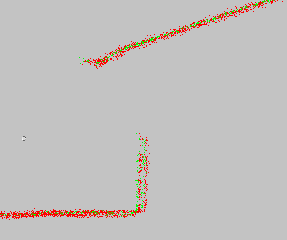
Create smart-projected cloud: Projects every original point to a computed surface. It keeps all the points from the cloud, but moves or 'projects' them to the computed surface.

Export data from curves
When enabled, this option includes data from turns within the generated pointcloud. The turn data point source ID is set to 0.
Create compressed Pointclouds
When enabled, this option outputs the generated pointcloud to a compressed LAZ 1.4 file instead of an uncompressed LAS 1.4 file.
GeoTiff DTM/DSM/CHM
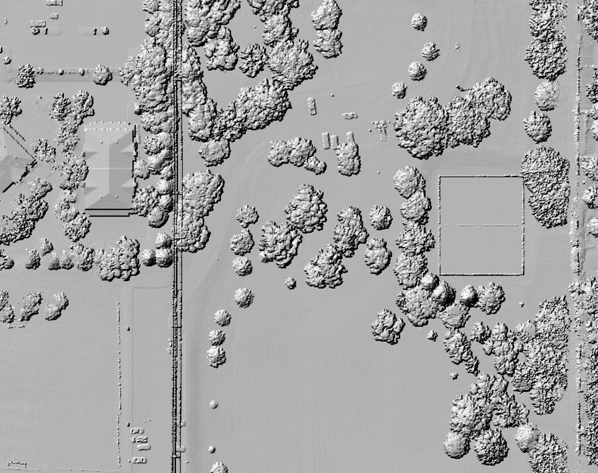
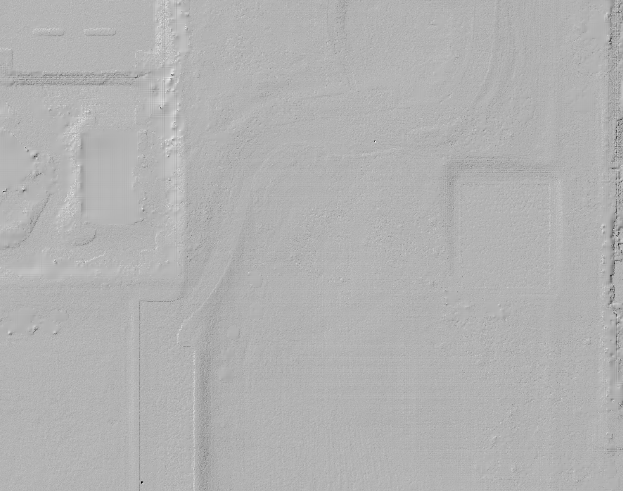
Option to output various products such as Digital Terrain Model (ground classified points only), Digitial Surface Model (Highest hit returns), and Canopy Height Model (Vertical distance offsets from ground model to highest hit returns). The output Geotiff files are georeferenced to the configured LM project CRS.
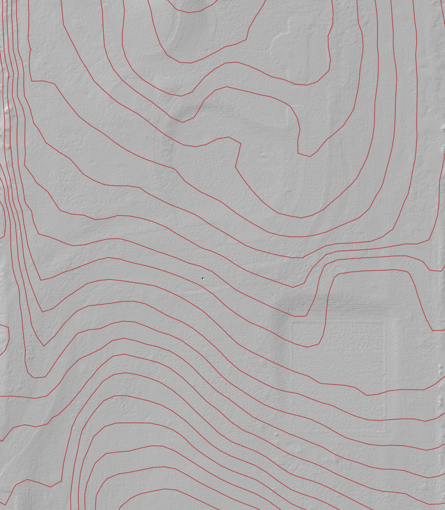
Contours
SHP/SHX/DBF/PRJ
Subsampled Pointcloud DTM
This option creates a downsampled pointcloud Digital Terrain Model (Based on ground classified points only, and based on the user specified grid stride)
Click "Finish" to initiate the pipeline.
Once created, view files and artifacts associated with the created pipeline under its "General" tab. When completed, the LAS/LAZ as well as the Project and Processing Reports can be located here. Under "Job Runs" check the progress of the Spatial Fuser pipeline.
LiDARMill processes your data in the cloud, so you can navigate to another screen within the application, visit another website, or close your browser, and post-processing will continue in the background. LiDARMill will automatically send you an email when processing is complete, if you selected that option when initiating the pipeline.
Last updated