Calibration Flight Strategy
Determining the X, Y, and Z location of a LiDAR return is strongly dependent on knowledge of the scanner's orientation and location at the time of firing the laser pulse. The scanner's orientation in respect to the center of navigation (usually the IMU) must be known to the thousandth of a degree if range measurements are to be made over long distances. This precise orientation can be solved reliably through the execution of a calibration flight. A proper calibration flight plan should consider the importance of flight location and data coverage in order to facilitate the determination of roll, pitch, and heading misalignments.
Location Selection
The calibration site should contain primarily hard surfaces and be free of vegetation. Flat, pitched structures, such as angled roofs and concrete structures, help the LiDAR optimization routine determine the alignment of the sensor, so it is important to pick a flight location with several buildings or structures. A well defined ground surface per each discrete flight-line will also allow for improvements in sensor alignment.
Requirements
Description
Camera calibration
Easily distinguishable photo-identifiable features (e.g. road paint markings)
LiDAR calibration
Elevated, pitched structures on flat hard ground surface
UAV Flight Plan
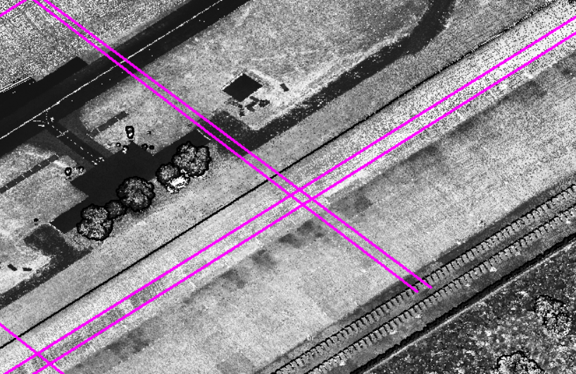
Follow this link to see an example calibration flight plan and trajectory (make sure to enable display of the trajectory under Scene -> Other -> Trajectory). A calibration flight plan should include at minimum two sets of opposing flight-lines. If possible, it is recommended to include four sets of opposing flight-lines, two at a lower AGL and two at a higher AGL. These sets should cross each other perpendicularly over an area that has man-made, pitched structures. Spacing between flight-lines should be 20 meters to ensure sufficient overlap in LiDAR data coverage between flight-lines. Click the download link below to view an example calibration flight with sets of opposing flightlines at 40 and 80 meters AGL.
In general, aircraft speed should be around 6 m/s for calibration missions. Sensor-specific acquisition settings and flight-line AGLs are listed in the tables below.
Riegl Sensors
Sensor
Lines per second
Laser Pulse Rate (KHz)
Lower Flightline AGL (m)
Upper Flightline AGL (m)
miniVUX-1UAV
37.5
100
40
70
miniVUX-2UAV
54
200
40
70
VUX-1UAV
68
550
60
120
VUX-1LR
83
820
60
120
VUX-1HA
113
1000
40
70
Velodyne and Hesai Sensors
When calibrating Velodyne sensors, return mode should be set to dual.
VLP16
1200
30
40
VLP32
1200
40
60 & 80
HDL32
1200
60
80
Pandar XT-32
600
60
80
Pandar XT-32M2X
600
60
80


Helicopter Calibration Flight Plan
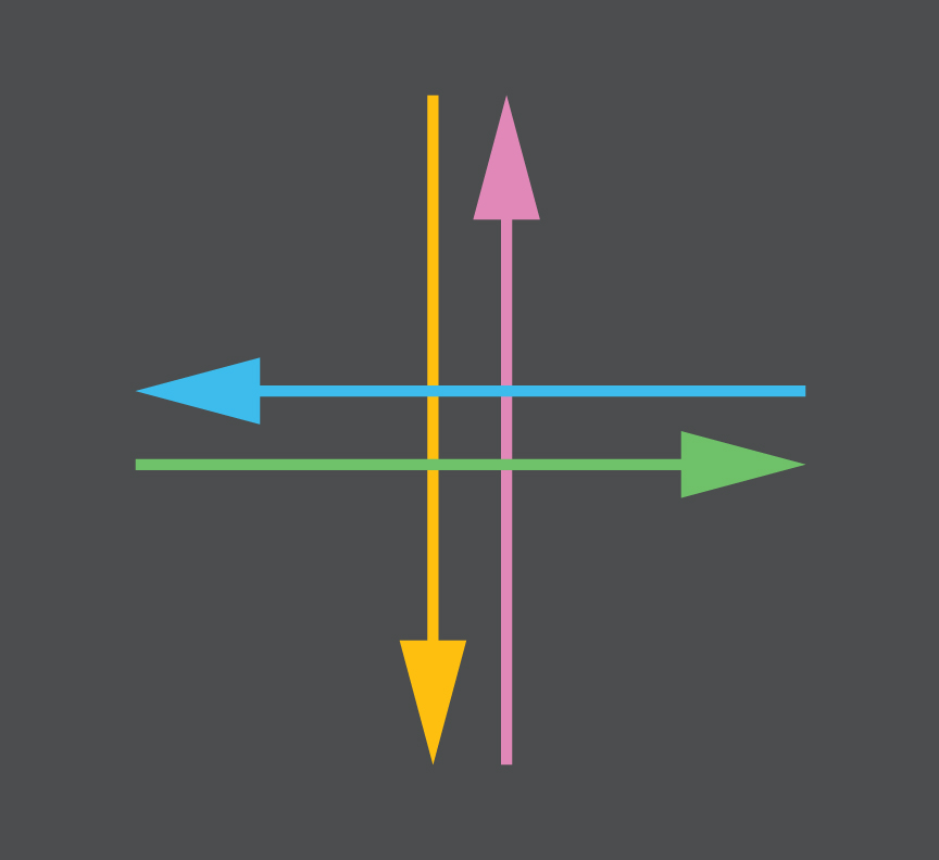
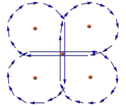
A calibration mission plan should include at minimum 2 sets of opposing flight-lines, intersecting each other perpendicularly. After you fly the first flight-line, only make right hand turns, which will result in the cloverleaf pattern shown in Figure 1 and Figure 2 below. Take care to ensure that the helicopter is flying straight and level through the intersection, and straight and level at least 100 meters before and after the intersection point. Flying the same pattern again at a different altitude will improve results.
The flight-line intersection should occur at the center of the street intersection, with the elevated planar features on the four corners of the street intersection, as shown in Figure 3 below.
For the Ranger systems we recommend flying the first cloverleaf at 100 meters AGL and the Second at 140 meters AGL at 820 kHz full power, and not exceeding 30 m/s. Set your camera triggering to allow for at least 75% image overlap for both cloverleaf flying altitudes.

Additional Considerations
Systematic misplacement of points due to sensor misalignment cannot be resolved beyond the accuracy of the trajectory, thus it is important to collect GNSS reference station observations during the calibration flight. Configure your reference station to record raw observations at 1 Hz. Try to include as many frequencies (L1, L2, L5) and constellations (GPS, GLONASS, Galileo, Beidou) in your reference station observations as possible.
Well defined above ground objects can be useful for visual verification of calibration adjustments. If you need to have the IMU and camera calibrated, make sure your camera is focused and set up properly before flight. Changing camera and lens properties after the flight will de-calibrate your camera.
Flight Execution
The calibration flight should include a proper IMU alignment routine. This must be performed BEFORE and AFTER the calibration scan. Follow the steps outlined in the checklist below to ensure the best trajectory and data capture. Refer to Field Scanning for more details on the procedure.
After powering on the rover (CPU light is green), if IMU is capable of static alignment, leave the system entirely static for 10 minutes. If not, leave it static for 3 minutes.
Take off and gain height until you reach a comfortable altitude.
Fly straight forward at a minimum velocity of 5m/s without changing heading over a distance of 100 meters and fly at least 3 figure-eights. Make sure to always keep the aircraft nose-forward.
Fly the calibration pattern, making sure to include a minimum of two sets of intersecting perpendicular flight lines. Make sure to fly the same pattern again at a different height (about 15 meters higher or lower if using a Scout or about 30 meters with a miniRanger or Ranger) to improve results.
Fly at least 3 figure-eights and then fly straight forward at a minimum velocity of 5m/s without changing heading over a distance of 100 meters. Make sure to always keep the aircraft nose-forward.
Land and perform static alignment routine for 10 minutes if applicable to your IMU. If not, then you can shut down rover 3 minutes after landing.
Required Data
Please upload the calibration data back to Phoenix LiDAR Systems using your LiDARMill account. If you do not have an account yet, please register and contact [email protected] to have your account activated.
Be sure to upload
the reference station observations (RINEX or binary data) covering the ENTIRE flight
the rover dataset (PLP, NAV, LOG, LDR or RXP, and camera data files). You can find this folder by accessing the rover’s \logs directory. Refer to Connect to Logs Directory for more information. If your system has an Air NavBox, you can also access Rover data via the removable micro SD card. Refer to Rover Data for more information.
a photo of the system's setup, how it is mounted to the vehicle and indicating which side of the vehicle faced forward
When you have uploaded the data, send an email to [email protected] so that we are notified of your upload.
Last updated