LiDARs and Cameras
In order to correctly georeference sensor measurements, the system needs to know how sensors are mounted relative to the IMU. This page describes these transforms.
In versions 1-5 of SpatialExplorer, translations and rotations of sensors were not relative to the IMU frame, but to a vehicle frame (X right, Y up, Z rear). This meant that when users were mounting their system to vehicles in unforeseen ways, each sensor's translation and rotation had to be updated. Starting with version 6, all transforms are relative to the IMU, so the system can be mounted in any orientation, without having to change IMU->camera or IMU->LiDAR transforms.
Thus, as long as the system is not disassembled and reassembled in a different way, all transforms remain constant, and the following explanations are not required for any procedures performed by the user.
When a sensor (e.g. LiDAR or camera) is initially configured to have a translation of X=0, Y=0, Z=0, that means its optical center (the point where the laser beam is emitted, or the nodal point of the camera's lens, respectively) coincides with the IMU's center of navigation.

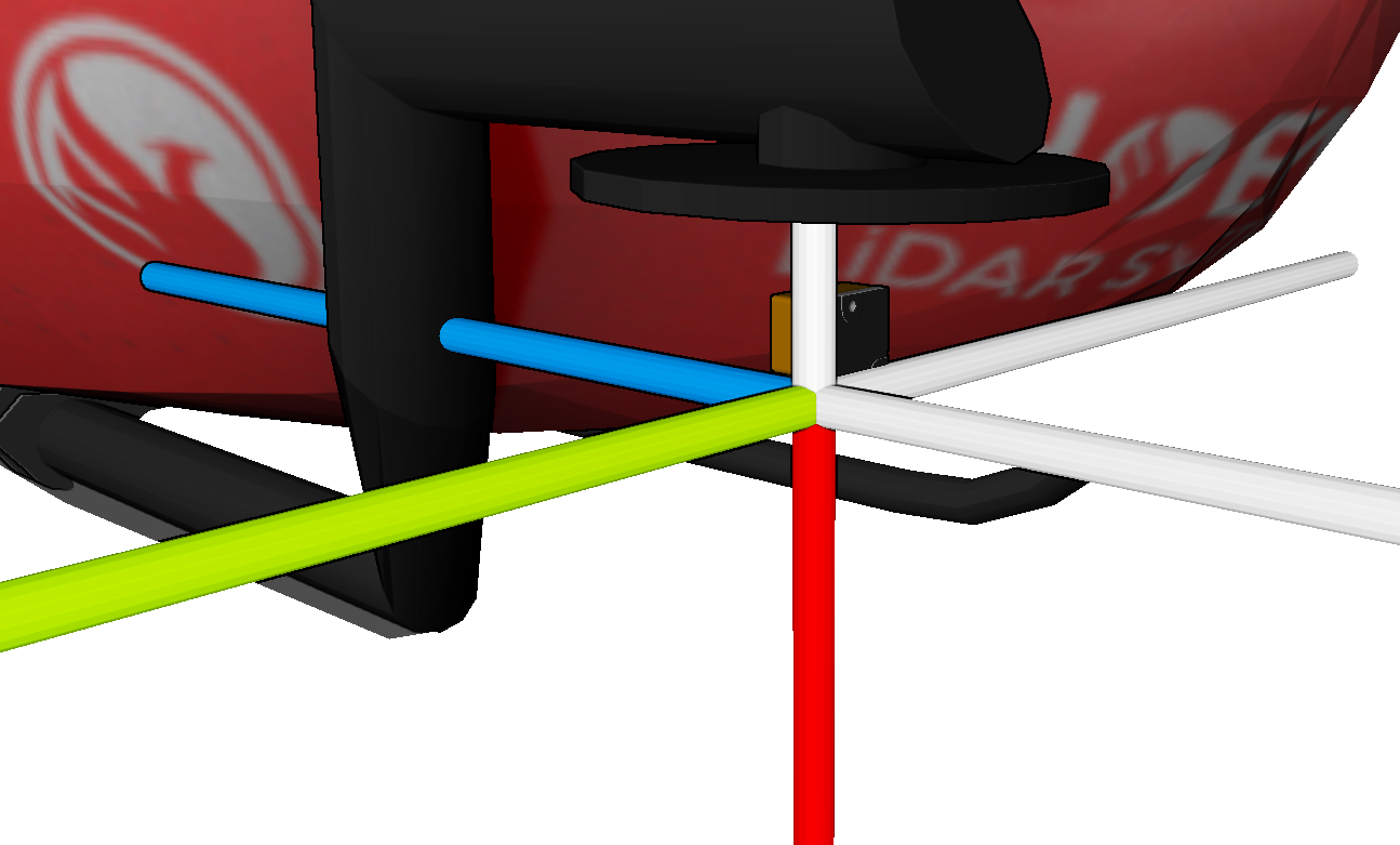
The image above shows an IMU-27 on a helicopter, with IMU-X (red) pointing vehicle-down, IMU-Y (green) pointing vehicle-right and IMU-Z (blue) pointing vehicle-rear.

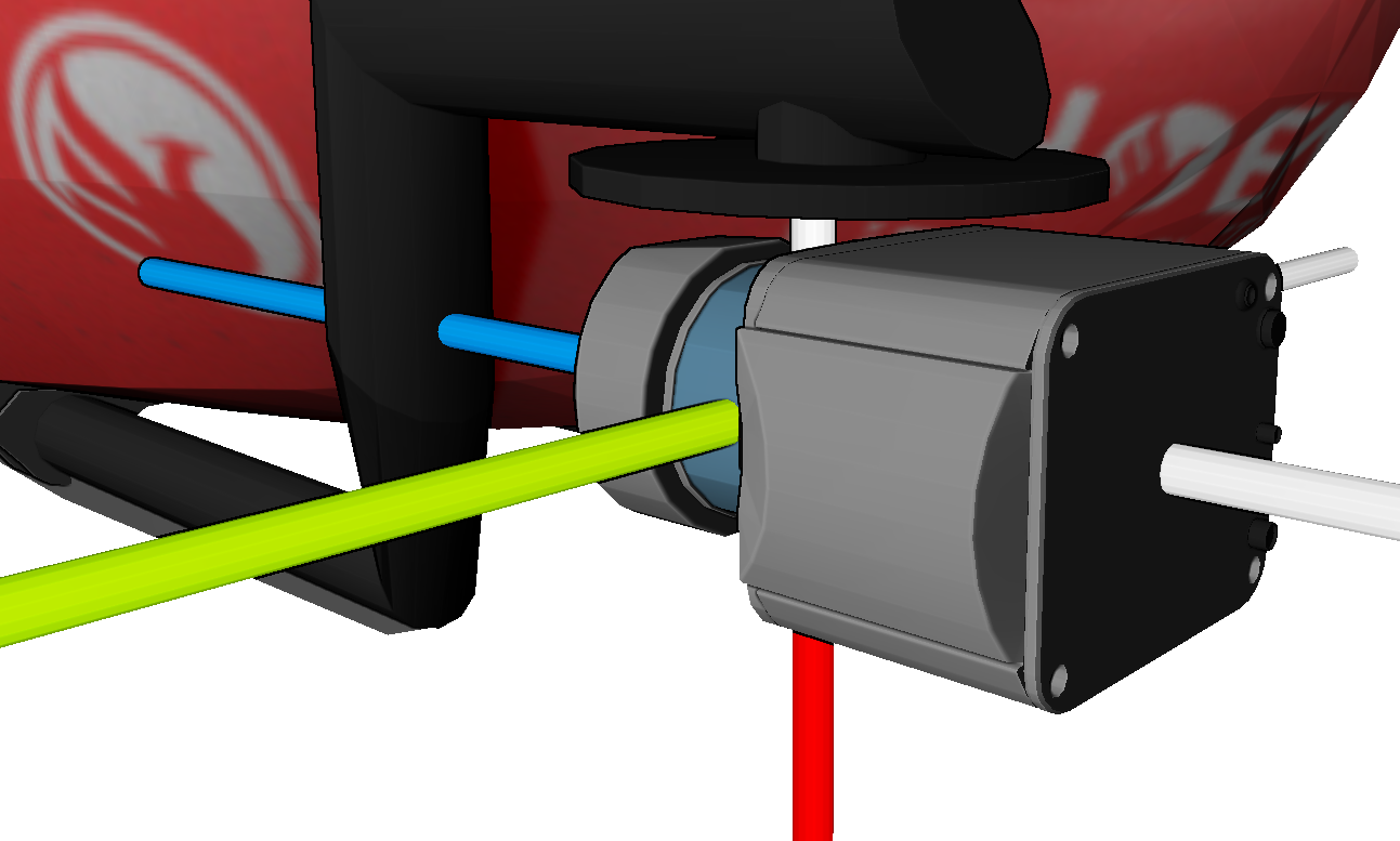
A LiDAR sensor was added with a translation of 0/0/0, so its optical center coincides with the IMU's center of navigation. That is of course mechanically impossible (or at least a very expensive exercise). Since the LiDAR's rotation values are all zero, its axes (as specified by the manufacturer) align with the IMU axes. That's not correct either.

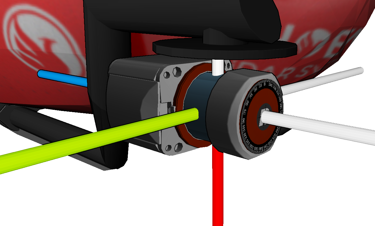
Now the sensor has been rotated 180 degrees around IMU-Y to arrive at its actual orientation. In general, the specified rotation needs to rotate the IMU axes into the sensor axes, rotating around fixed IMU-X, IMU-Y, IMU-Z axes, in that order (in this example the order didn't really matter, because we only rotated around one axis).

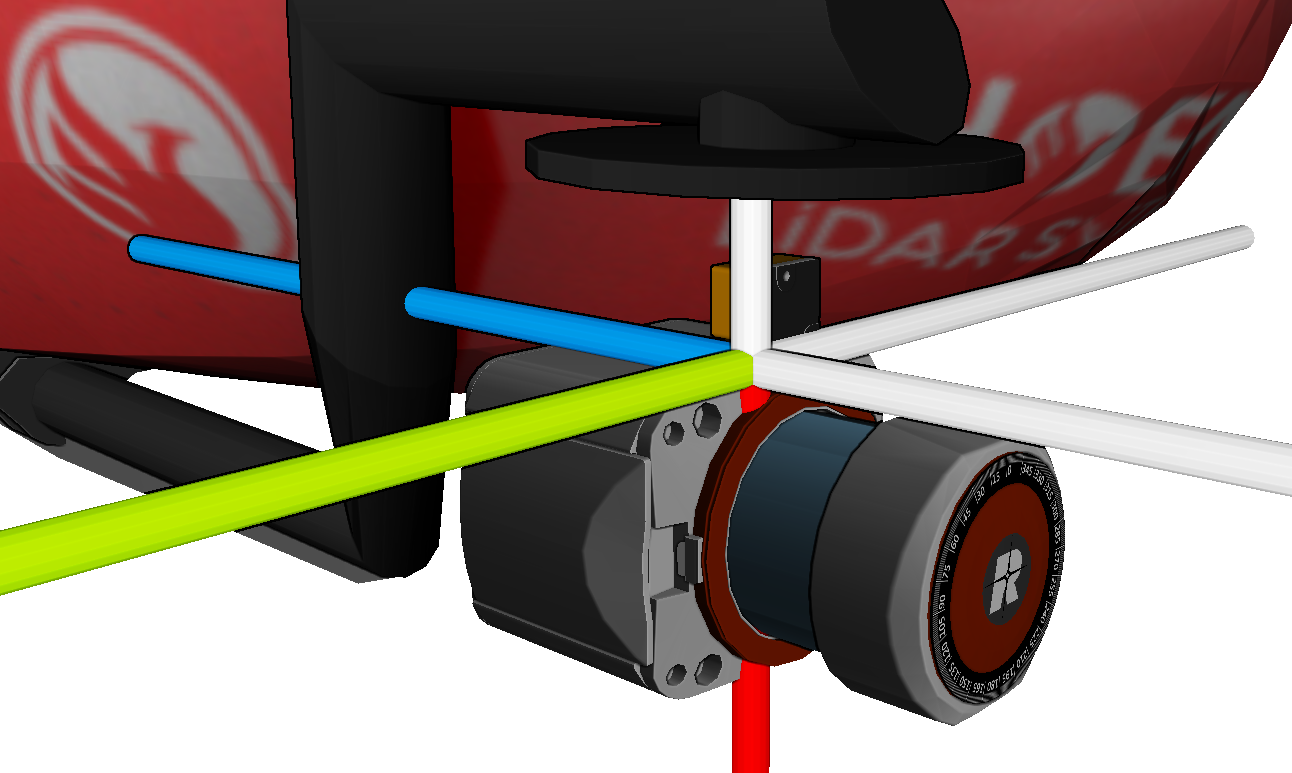
Finally, the LiDAR is translated along IMU axes: 0.064m along IMU-X, -0.022m along IMU-Y and -0.042m along IMU-Z. Now it matches the actual setup.
All cameras share the same coordinate axis convention: X points image-right, Y points image-down and Z points through the lens at the scene (matching the OpenCV convention). However, different LiDAR sensors have different axis orientations, so it's best to use SpatialExplorer's 3D visualization to verify the sensor's orientation.
Last updated