GNSS Antennas
It is extremely important to measure the offsets from the IMU’s center of navigation to the GNSS antenna L1 phase center. These measurements will be your IMU to GNSS antenna offsets.
Custom Profile Creation
The following steps are useful if you want to measure your own offsets so that you can create a new custom profile here. This can be helpful if you have made a modification to your vehicle that you don't want to wait for our engineering team to verify and confirm, if you do not have PLS Care, or if you simply want to reconfirm lever arms yourself.
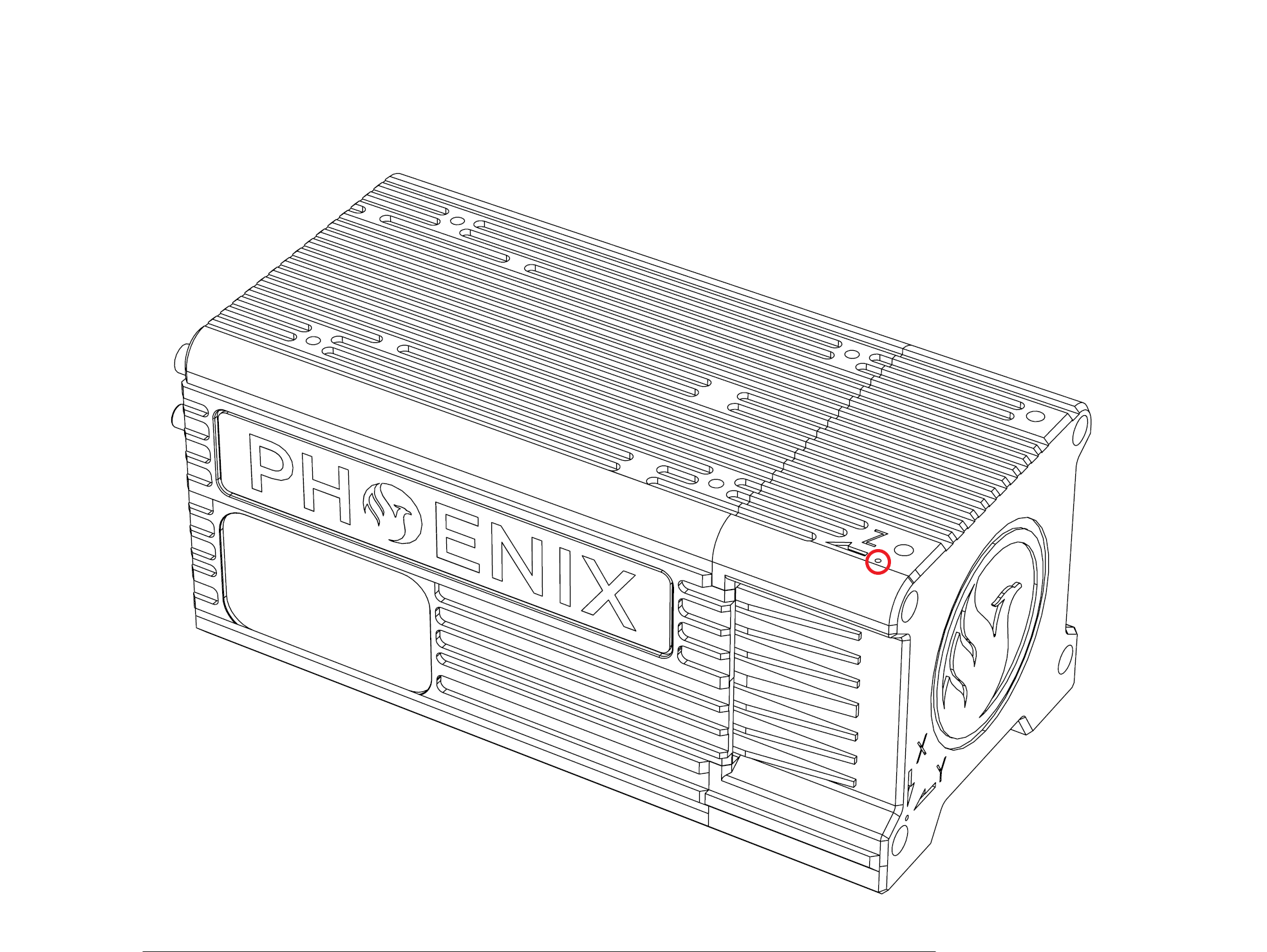
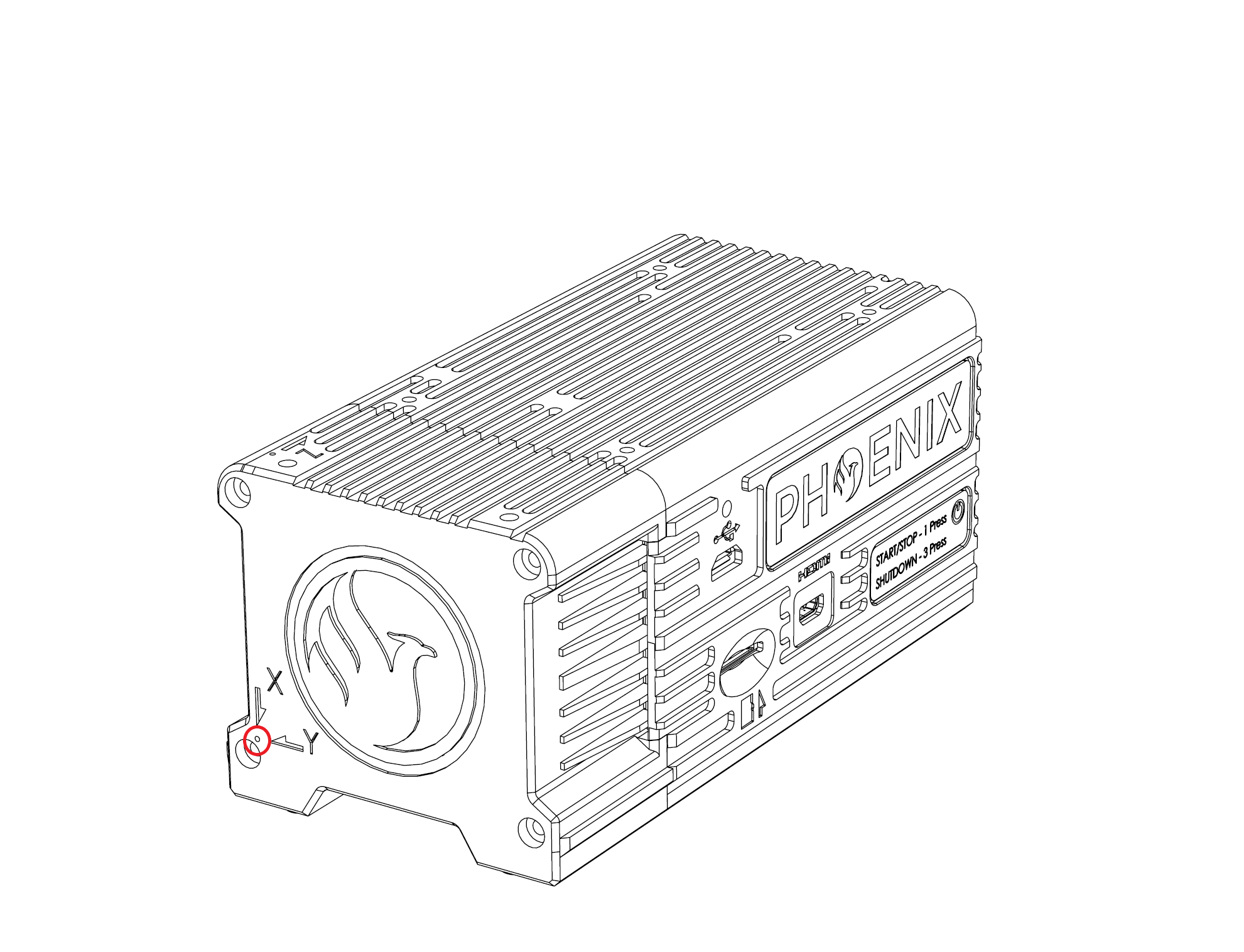
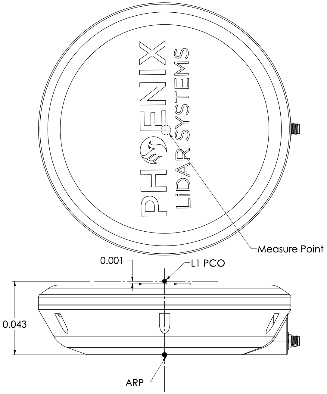
1. Locate the GNSS antenna L1 Phase center and the IMU center of navigation. The location of the antenna L1 phase center can be found in the antenna’s datasheet. If using the Rover GPS Antenna supplied by Phoenix LiDAR Systems, refer to the drawing below for the location of the L1 Phase center. The IMU's point of reference and directional axes are displayed on the IMU/enclosure label or NavBox enclosure as shown in the example pictures below.
In the below example, the two points in the first two photos indicate the intersecting lines that determine the IMU point of reference, and the X, Y, and Z arrows indicate the positive direction of those axes.


If the measurement is in the positive direction of the IMU axis, the recorded value will be positive; if the measurement is in the opposite direction of the axis, the recorded value will be negative.
2. Measure the distance from the IMU center of navigation to the GNSS antenna L1 phase center (not the other way around) along each axis of the IMU and record the measurements. The easiest way with most antenna is to measure to ARP (Antenna Reference Point) which is usually the center point at the bottom of the antenna, and then add the known offset to the L1PC.

3. Open the Orientation & Offsets settings in SpatialExplorer located in Rover → Settings → Navigation System.
4. Update the “Offset IMU to Antenna 1” parameters with the recorded measurements obtained in step 2 for the X, Y, and Z axes. The entered values must be in meters. If your measurements are in centimeters or millimeters, you must convert them to meters.
5. If the system has a second antenna, repeat the procedure for the second antenna. Ensure that you are measuring the offsets to the correct antenna (antenna 1 is the antenna connected to GPS1, antenna 2 is connected to GPS2).
6. Save the current profile settings in SpatialExplorer.
7. In order for the updated IMU to GNSS antenna offsets to take effect, you must restart the rover. Just click the "Shutdown Rover" button in SpatialExplorer or use the web interface. You can also press the button on the enclosure to power cycle the system.
Factory Profile Requests
If you have a PLS Care subscription for your system, you can request for our engineering department to add a new factory profile to that system. This is most helpful if you introduce and entirely new vehicle type to your workflow, and want to validate your measurements with our engineering team.
Take photographs of all angles showing how your system is mounted and where it is in respect to the antenna/antennas.
Send these photographs to [email protected] along with the desired name of the factory profile and any further details such as expected vehicle speed, altitudes, and measurement speed.
Our support team will send a form with measurement instructions for you to fill out. This measurement will be slightly easier than the custom profile since it is from the dovetail center to L1PC instead of the IMU center to L1PC.
Once we receive your measurements, our engineering team will verify and confirm the values and then create the factory profile.
Our support team will then remotely perform a system reset, upon which the new factory profile will be installed.
Last updated