IMU
The system’s frame of reference is the IMU (which is why the reference point in the IMU is named the “center of navigation”). All other sensors' (e.g. GNSS antennas, cameras, LiDAR sensors) transforms are specified relative to the IMU's position and orientation.
IMU Position
The position of the IMU center of navigation does not need to be defined. Instead, the position of all other sensors are defined relative to the IMU’s center of navigation.
IMU Orientation
The orientation of the IMU must be defined relative to the vehicle’s orientation. In other words, the IMU orientation defines the direction of the IMU X, Y, and Z axes relative to vehicle-forward, vehicle-right and vehicle-up. Let us first find out how IMU axes are documented.
External IMUs
All Phoenix LiDAR Systems external IMUs include labels indicating the positive direction of all three axes (X, Y, Z) and the location of their origin (also known as the center of navigation of the IMU).
Internal IMUs
Phoenix LiDAR Systems offers the Scout Series mapping solution. Unlike the other mapping solutions offered by Phoenix LiDAR Systems, the Scout features an internal IMU as opposed to external. At the time of writing, the Scout Series supports the IMU-27 and IMU-14.
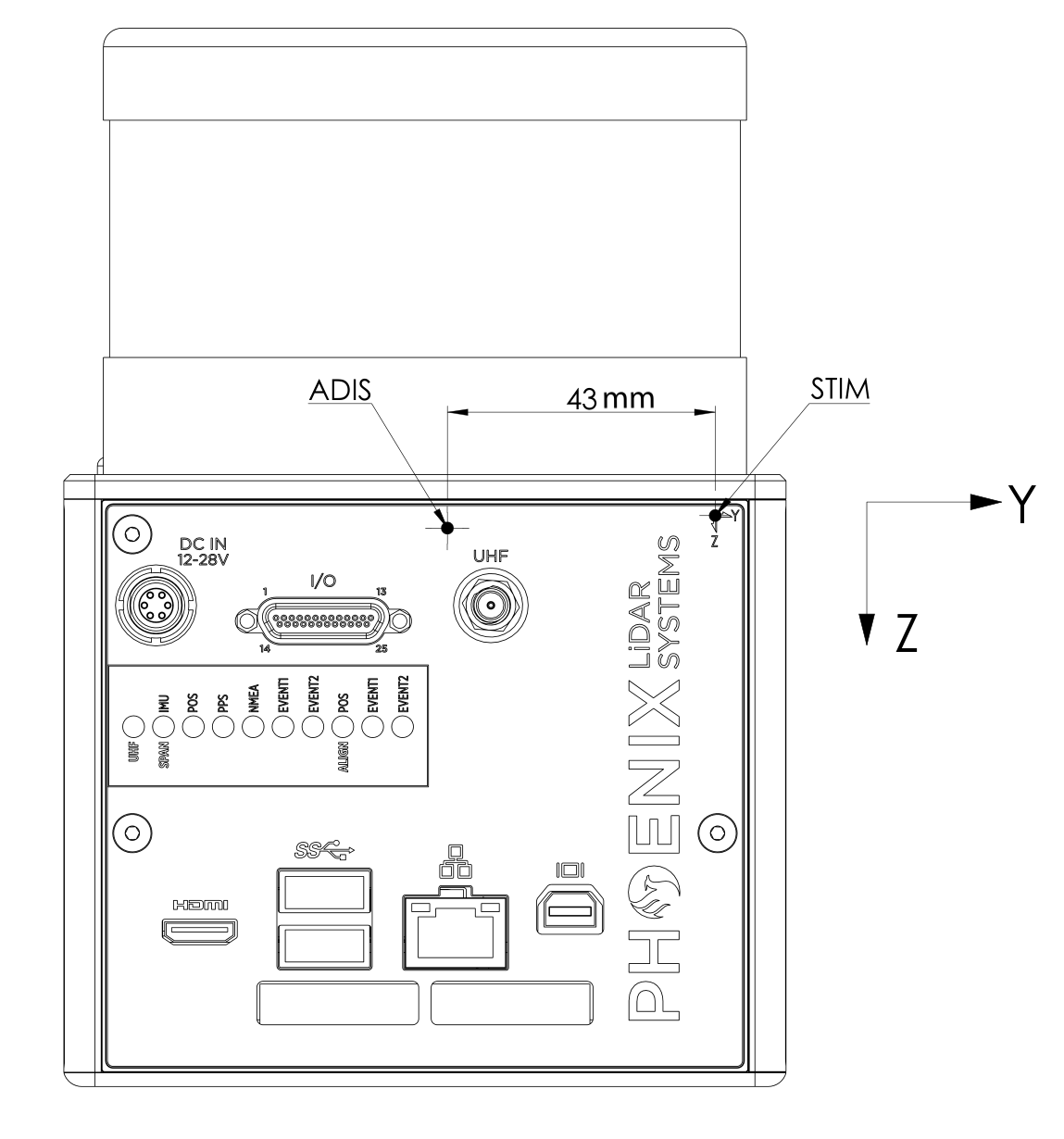
Instead of an IMU label, the Scout has markings on the outside of the NavBox enclosure indicating the positive direction of the axes and the center of navigation. The positive directions of the Y and Z axes are indicated on the top-right corner on the front of the box and the positive direction of the X axis is indicated on the top-left corner on the side of the box.
In general, the center of navigation of any IMU is always the origin of the X, Y and Z axes as defined on the IMU label or rover-enclosure. For the Scout Series, the X axis center of navigation depends on the type of internal IMU. If your Scout has an IMU-14, the center of navigation for the X axis is the dot located above the IMU-14 marking. If your Scout rover has an IMU-27, the center of navigation for the X axis is the dot located above the IMU-27 marking. Notice the vertical distance offset between the IMU-27 and IMU-14 center of navigation; the IMU-27 center of navigation is a few millimeters above the IMU-14 center of navigation.

Determining IMU Orientations
The difficulty in determining IMU orientations is that imagining a sequence of rotations around a set of axes is simple, but explaining it for others to reproduce exactly is hard. So let us first define some basics:
When rotating an IMU around its axes, it is very important in which order that rotation is performed. First rotating e.g. 90 degrees around X, then 90 degrees around Y will result in a different orientation than first rotating the same amounts around Y, then X.
When performing rotations around more than one axis, it is important to specify whether the second and third rotations rotate around the initial/fixed axes, or whether they rotate around the rotated axes. The former style is called extrinsic rotation, the latter intrinsic rotation.
When rotating around an axis, we always follow the right-hand rule: using your right hand, your thumb points in the direction of the axis you rotate around, and your fingers will curl in the direction of positive rotation. A negative rotation will rotate against the direction of your fingers.

Just to make things even more complicated, every navigation system vendor follows a different set of conventions. For example, NovAtel's OEM6 series of navigation systems use a different convention than NovAtel's OEM7 series, and that again differs from NovAtel's Inertial Explorer. To read more about OEM6 and IE, please see this document.
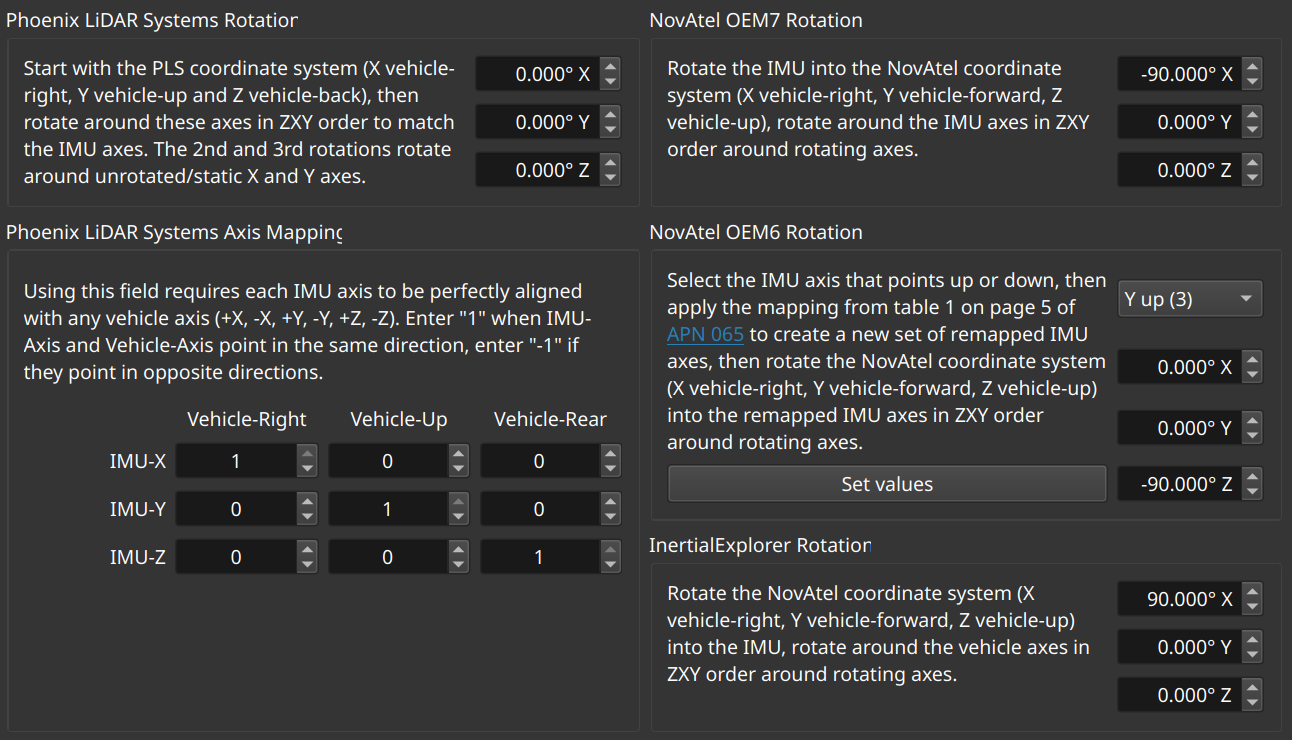
To make this task manageable, our SpatialExplorer desktop software contains a helpful tool, to be found under Tools->Navigation->Convert IMU Orientation:

This dialog allows you to enter the IMU orientation in any convention, either to configure the system, or simply to convert these orientations if that is ever needed in post-processing.
For the majority of times when all IMU axes align with vehicle axes (i.e., no 30-degree rotations for mobile mapping setups), you should use the 3x3 matrix shown in the bottom left. In the dialog shown, the IMU-X axis points vehicle-right, so the top-left field (matching IMU-X/vehicle-right) contains a 1. If IMU-X pointed the opposite way, so, vehicle-left, this field should contain a -1. Continuing with the other IMU axes, since IMU-Y points vehicle-up, the center field contains a 1, and because IMU-Z points towards the vehicle-rear, the bottom-right field contains a 1.

Orientation Example A. IMU-axes X, Y, Z are shown in red, green, blue, respectively. X points vehicle-right, Y points vehicle-up and Z points vehicle-rear. In Inertial-Explorer, this would be X=90, Y=0, Z=0.

Orientation Example B: IMU-axes X, Y, Z are shown in red, green, blue, respectively. X points vehicle-up, Y points vehicle-right and Z points vehicle-forward. In Inertial-Explorer, this would be X=180, Y=90, Z=90.
There are many ways to store and process orientations/rotations in a computer; e.g. matrices, quaternions or euler angles. The dialog shown above will parse the orientation the user enters, transform it into an internal representation and back into the other conventions shown. In that process, it is entirely possible that a user-entered rotation of e.g. X=-90, Y=270, Z=180 becomes X=0, Y=180, Z=-90. This may be very unintuitive for humans, but it still is correct.
Last updated